Owner’s manual
Assembly & operating instructions
The Workin’ Collapsible Wheelbarrow, start to finish: what’s in the box, six steps to build it, three to fold it flat, and what to check before every load. Same content as the printed sheet that came with yours.
The PDF is for printing or keeping offline. Everything in it is on this page.
What’s in the box
Lay everything out and check it off before you start. All connecting hardware is metal — no plastic hardware is supplied.
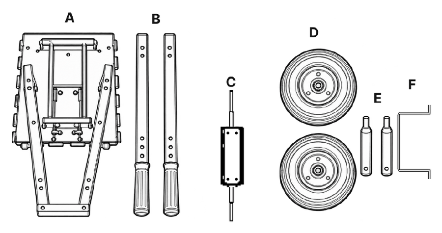
Frame components
- A — Main Frame ×1
- B — Handle ×2
- C — Axle Bracket ×1
- D — Pneumatic Wheel ×2
- E — Wheel-Mounting Pin ×2
- F — U-Shaped Retaining Bracket ×1
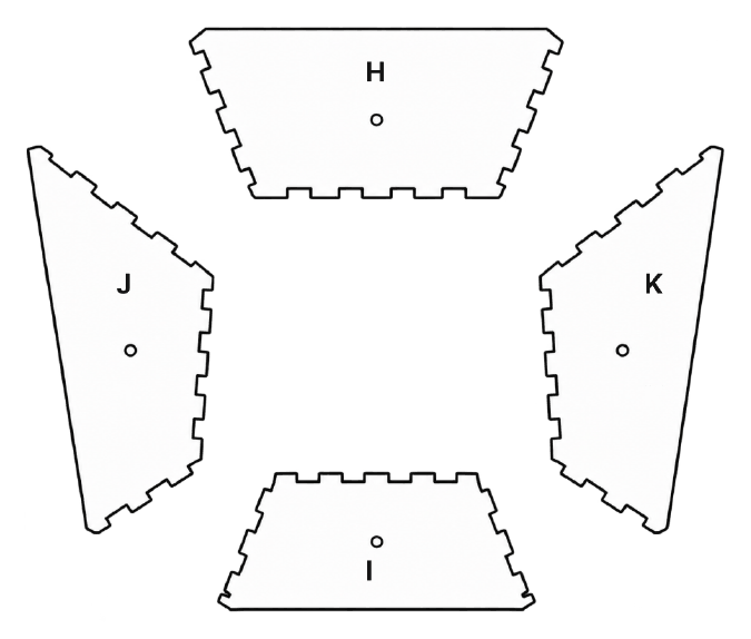
Tub components
- H — Front Panel ×1 (larger)
- I — Rear Panel ×1 (smaller)
- J — Left Side Panel ×1
- K — Right Side Panel ×1
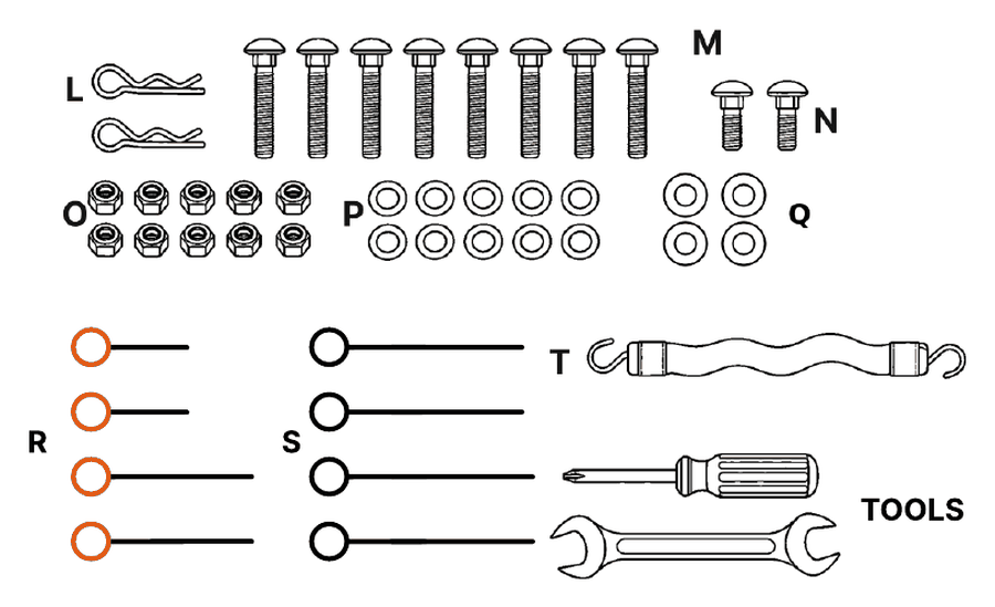
Connecting hardware
- L — Hairpin Cotter Pin ×4
- M — Long Carriage Bolt ×8
- N — Short Carriage Bolt ×2
- O — Locknut ×10
- P — Small Flat Washer ×10
- Q — Large Flat Washer ×4
- R — Orange-Ring Rods ×4 (2 long / 2 short)
- S — Black-Ring Rods ×4 (2 long / 2 short)
- T — Storage Strap ×1
- Tools — Phillips screwdriver + open-end wrench
Before assembly: check that the frame, five tub panels, two handles, two wheels, axle bracket, two wheel-mounting pins, U-shaped retaining bracket, eight connecting rods, fasteners, the strap and both tools are present.
Building it: six steps
Work in order — each step leaves the frame steady for the next one. Everything you need is in the box, including both tools.
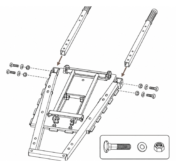
Install the handles
Slide handles B into both frame sockets in the direction shown. Align both holes on each side. Secure each handle with 2 long carriage bolts M, 2 small flat washers P and 2 locknuts O. Tighten with the supplied wrench.
Check Both handles are fully tightened, aligned and free from looseness.
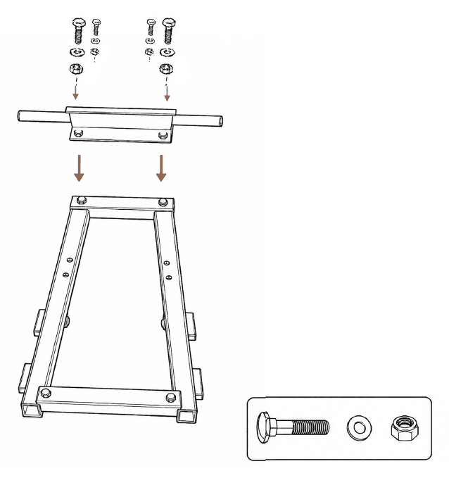
Install the axle
Position the axle assembly across the narrow end of the main frame as shown. Align all four mounting holes. Insert 2 long carriage bolts M through the two outer holes and 2 short carriage bolts N through the two inner holes. Fit 4 small flat washers P and 4 locknuts O from below, then tighten with the supplied wrench.
Check The axle assembly is centered, fully tightened and firmly secured with no looseness.
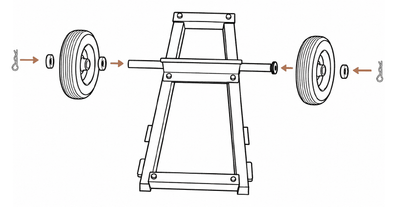
Install the wheels
Fix axle bracket C to frame A with 4 long bolts M, 4 small washers P and 4 locknuts O. Screw wheel-mounting pins E into both axle ends and tighten. Slide on wheels D, then fit one large washer Q and one hairpin cotter pin L at each outer end.
Check Rotate both wheels by hand. They must turn freely without excessive side play.
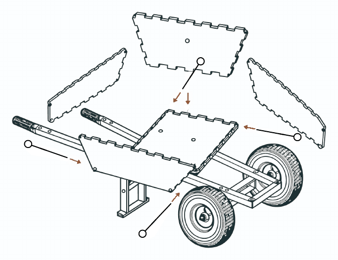
Position the tub panels
Set panels H–K around base G. Place the larger front panel H at the tall end and the smaller rear panel I at the low end. Match every finger joint before inserting black-ring rods. Shorter black-ring rods are at the front & back. Longer black-ring rods are at the sides.
Check H and I are not interchangeable.
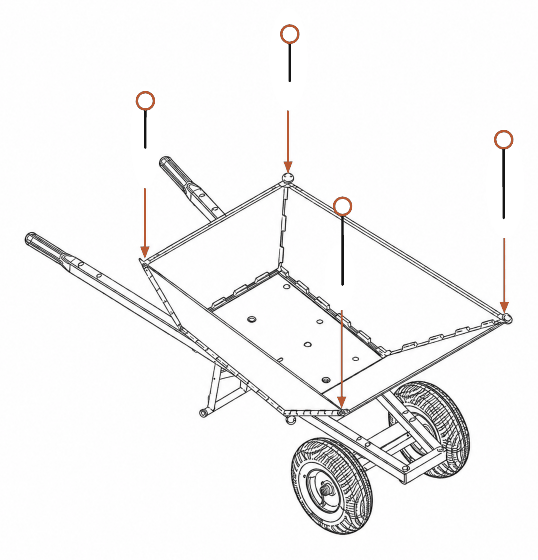
Lock the corner rods
Insert 4 orange-ring rods R vertically through the corner hinge loops: 2 long rods at the taller front corners and 2 short rods at the lower rear corners.
Check All 8 rods are fully inserted; the tub walls are square and secure.
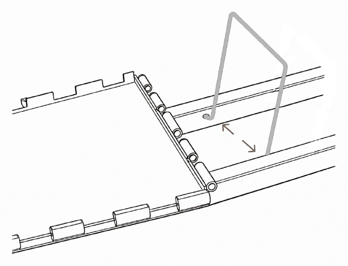
Install the U-shaped retaining bracket
Fit U-shaped retaining bracket F between the two frame rails beside base G. Insert its two bent ends into the matching holes on the inner faces of the rails as shown.
Check Both ends are fully secured in the frame holes.
Assembly check Tighten all fasteners, fully unfold the pre-installed support leg, and confirm every moving part operates freely. Confirm front panel H is larger than rear panel I, and that all 8 rods pass through every aligned hinge loop.
Folding it flat
Three moves, no tools. Putting it back together is the same steps in reverse — remember the colors: orange rings at the tub corners, black rings at the base.
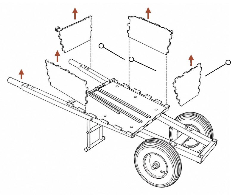
Remove the tub and store the rods
Empty and clean the tub. Pull out the 4 orange-ring corner rods R and the 4 black-ring bottom rods S. Lift away panels H–K and keep all rods together.
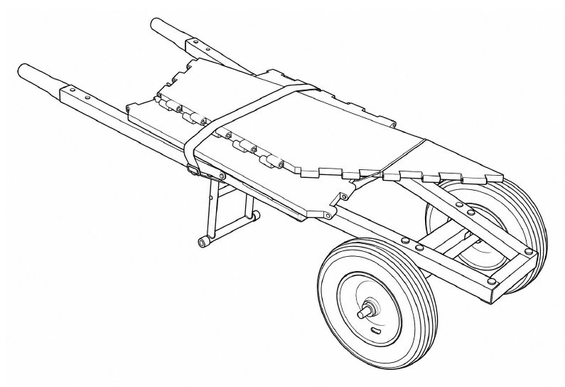
Stack and secure
Lay panels H–K flat over base G in the order shown. Wrap the storage strap T around the stack and tighten it so the panels cannot slide.
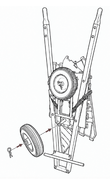
Fold and store upright
Fold the pre-installed support leg against frame A. Lift the compact cart to the vertical position shown and secure it to prevent tipping. Do not leave it free-standing where it may fall.
Storage check The panel stack must be strapped tightly, and the upright cart must be secured against tipping.
Warning
Read all instructions before use
- Do not overload the wheelbarrow.
- Do not carry passengers.
- Do not dump on slopes.
- Keep hands away from collapsible joints.
- Keep people away from the front of the tub during dumping.
- Avoid impacts that may damage plastic panels.
Maximum load: 250 lbs (113 kg). Do not exceed.
Overloading beyond the 250-pound rated capacity, or loading unevenly, can cause the wheelbarrow to tip over or cause the tray, frame, handles, wheel, tire, or axle to bend, crack, or fail. This can result in serious personal injury and property damage.
To reduce the risk of injury:
- Never load the wheelbarrow with more than 250 lbs total.
- Distribute the load evenly and keep it low and centered over the wheel.
- Keep the tire inflated to the recommended pressure and keep all fasteners tight.
- Read and follow all product instructions before use.
- Do not allow children to ride in or play on the wheelbarrow.
Loading beyond the rated capacity or failing to follow these instructions may also void your Limited Warranty.
Before each use
Check
- Wheel condition
- Tire pressure
- Loose fasteners
- Pivot points
- Retaining clips
- Tub connection points
Lubricate
- Wheel axle points
- Tub pivot points
- Moving joints
Regular lubrication helps maintain smooth operation.
Troubleshooting
- Tub does not lock
- Check pivot alignment, locking pins and retaining clips.
- Wheel is loose
- Check the wheel axle, the large flat washer and the hairpin cotter pin.
- Frame connection is loose
- Check bolts, locknuts and washers.
Still stuck?
Tell us which step you’re on and what isn’t lining up. We started building this thing out of cardboard, so there isn’t a question about it we haven’t already asked ourselves.
Get in touchcontact@rockinjinnovations.com
Or call 877-536-5192
Collapsible Wheelbarrow · Model 42100 Master Assy